瑞斯克石英晶体振荡器说明书,随着电子行业的产品越来越多元化,为了更好顺应市场的变化,Crystek公司利用自身的优势,针对目前振动器产品进行深入研究与探索说明,并研发设计出极具有价值的石英晶体振荡器,并因此吸引了广泛用户的关注,产品融合的高质量低抖动低电压的特点,可以满足不同应用程序的需求,同时也优化相噪声,又获得极好的用户体验。
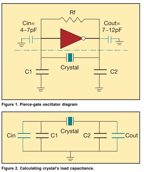
图1中的皮尔斯门振荡器得到了大多数设计师的认可,但很少有人了解如何正确指定晶体。拓扑结构中使用的晶体图1可以是基本的AT-CUT或BT-CUT。BT-CUT晶体质量差与AT-CUT相比,频率随温度的稳定性。此拓扑使用平行晶体而不是串联晶体。当指定平行晶体时,晶体制造商还将要求您指定负载电容。
要了解负载电容,请考虑串联LC电路,其中晶体是L,负载电容是C。谐振LC电路的频率将作为L和C的函数而变化在晶体情况下,L是固定的(温度不是参数)。瑞斯克石英晶体振荡器说明书.
晶体数据表上的参数由负载电容是25°C时中心频率的公差或校准。如果有源晶体振荡器电路设计不匹配负载电容值,则中心频率将不在数据表的公差限制。有趣的是并联晶体要求其电容负载有效串联其端子。
那么,您的皮尔斯门振荡器向结晶如图2所示的一个简单计算将告诉您。
图2中大多数设计师忽略的最重要的事实是反相器门的内部输入和输出电容。这些与外部(C1和C2)相比在值上是显著的。如果Cin和Cout没有指定,那么每个5 pF的猜测值是好的开始以后可以通过改变启动来优化电路C1和C2的值。所以,不要放弃你的主要宽容;计算您的振荡器电容负载。
既然你知道了如何计算负载电容电路呈现给水晶,您应该选择什么负载电容?在回答这个问题之前,你需要知道晶体中心频率对负载的灵敏度电容。这被称为微调灵敏度S,由下式给出:

其中Cm是晶体的运动电容,
Co是晶体的分流电容,
Cload是负载电容。
从修剪灵敏度方程中,你可以看到,你制作的Cload越小,就越大微调灵敏度。换句话说,如果你正在设计一个固定频率的时钟,那么你选择一个高的Cload值,比如20 pF。但是,如果你正在设计一个可变频率振荡器(VCXO)选择诸如14pF的低Cload值。瑞斯克石英晶体振荡器说明书.
C1和C2的值也影响有源晶振的增益。值越低,越高增益。同样,C2/C1比率也会影响增益。要增加增益,请使C1小于C2.
原厂代码
品牌
型号
类型
频率
频率稳定度
工作温度
CCHD-575-25-22.5792
Crystek振荡器
CCHD-575
XO (Standard)
22.5792MHz
-
0°C ~ 70°C
CCHD-575-50-125.000
Crystek振荡器
CCHD-575
XO (Standard)
125MHz
±50ppm
0°C ~ 70°C
CCHD-950-50-49.152
Crystek振荡器
CCHD-950
XO (Standard)
49.152MHz
±50ppm
0°C ~ 70°C
CCPD-575X-20-80.000
Crystek振荡器
CCPD-575
XO (Standard)
80MHz
±20ppm
-40°C ~ 85°C
CCHD-957-25-24.576
Crystek振荡器
CCHD-957
XO (Standard)
24.576MHz
±25ppm
0°C ~ 70°C
CCHD-957-25-45.1584
Crystek振荡器
CCHD-957
XO (Standard)
45.1584MHz
±25ppm
0°C ~ 70°C
CCHD-957-25-49.152
Crystek振荡器
CCHD-957
XO (Standard)
49.152MHz
±25ppm
0°C ~ 70°C
CCPD-575X-20-125.000
Crystek振荡器
CCPD-575
XO (Standard)
125MHz
±20ppm
-40°C ~ 85°C
CCSO-914X-245.760
Crystek振荡器
CCSO
SO (SAW)
245.76MHz
±150ppm
-40°C ~ 85°C
CVHD-952-153.600
Crystek振荡器
CVHD-952
VCXO
153.6MHz
-
0°C ~ 70°C
CVSS-945-125.000
Crystek振荡器
CVSS-945
VCXO
125MHz
-
0°C ~ 70°C
CVS575-500.000
Crystek振荡器
CVS575
VCSO (SAW)
500MHz
±150ppm
-20°C ~ 70°C
CRBSCS-01-100.000
Crystek振荡器
CRBSCS, RedBox
RF Clock Source
100MHz
±150ppm
-40°C ~ 85°C
CPRO33-50.000
Crystek振荡器
CPRO
XO (Standard)
50MHz
±25ppm
0°C ~ 70°C
CPRO33-125.000
Crystek振荡器
CPRO
XO (Standard)
125MHz
±25ppm
0°C ~ 70°C
CRBSCS-01-125.000
Crystek振荡器
CRBSCS, RedBox
RF Clock Source
125MHz
±25ppm
-40°C ~ 85°C
CRBSCS-01-50.000
Crystek振荡器
CRBSCS, RedBox
RF Clock Source
50MHz
±25ppm
-40°C ~ 85°C
CRBSCS-01-245.760
Crystek振荡器
CRBSCS, RedBox
RF Clock Source
245.76MHz
±150ppm
-40°C ~ 85°C
PPRO30-13.000
Crystek振荡器
PPRO
TCXO
13MHz
±2.5ppm
-20°C ~ 75°C
PPRO30-26.000
Crystek振荡器
PPRO
TCXO
26MHz
±2.5ppm
-20°C ~ 75°C
CPRO33-156.250
Crystek振荡器
CPRO
XO (Standard)
156.25MHz
±25ppm
-40°C ~ 85°C
CVHD-950X-122.880
Crystek振荡器
CVHD-950
VCXO
122.88MHz
-
-40°C ~ 85°C
C3290-1.544
Crystek振荡器
C3290
XO (Standard)
1.544MHz
±100ppm
0°C ~ 70°C
C3290-1.843200
Crystek振荡器
C3290
XO (Standard)
1.8432MHz
±100ppm
0°C ~ 70°C
C3290-10.000
Crystek振荡器
C3290
XO (Standard)
10MHz
±100ppm
0°C ~ 70°C
C3290-12.000
Crystek振荡器
C3290
XO (Standard)
12MHz
±100ppm
0°C ~ 70°C
C3290-12.288
Crystek振荡器
C3290
XO (Standard)
12.288MHz
±100ppm
0°C ~ 70°C
C3290-12.352
Crystek振荡器
C3290
XO (Standard)
12.352MHz
±100ppm
0°C ~ 70°C
C3290-14.318180
Crystek振荡器
C3290
XO (Standard)
14.31818MHz
±100ppm
0°C ~ 70°C
C3290-15.360
Crystek振荡器
C3290
XO (Standard)
15.36MHz
±100ppm
0°C ~ 70°C
C3290-16.000
Crystek振荡器
C3290
XO (Standard)
16MHz
±100ppm
0°C ~ 70°C
C3290-16.384
Crystek振荡器
C3290
XO (Standard)
16.384MHz
±100ppm
0°C ~ 70°C
C3290-18.432
Crystek振荡器
C3290
XO (Standard)
18.432MHz
±100ppm
0°C ~ 70°C
C3290-19.440
Crystek振荡器
C3290
XO (Standard)
19.44MHz
±100ppm
0°C ~ 70°C
C3290-2.048
Crystek振荡器
C3290
XO (Standard)
2.048MHz
±100ppm
0°C ~ 70°C
C3290-20.000
Crystek振荡器
C3290
XO (Standard)
20MHz
±100ppm
0°C ~ 70°C
C3290-20.480
Crystek振荡器
C3290
XO (Standard)
20.48MHz
±100ppm
0°C ~ 70°C
C3290-24.000
Crystek振荡器
C3290
XO (Standard)
24MHz
±100ppm
0°C ~ 70°C
C3290-24.704
Crystek振荡器
C3290
XO (Standard)
24.704MHz
±100ppm
0°C ~ 70°C
C3290-25.000
Crystek振荡器
C3290
XO (Standard)
25MHz
±100ppm
0°C ~ 70°C
C3290-3.686400
Crystek晶振
C3290
XO (Standard)
3.6864MHz
±100ppm
0°C ~ 70°C
C3290-30.000
Crystek振荡器
C3290
XO (Standard)
30MHz
±100ppm
0°C ~ 70°C
C3290-32.000
Crystek振荡器
C3290
XO (Standard)
32MHz
±100ppm
0°C ~ 70°C
C3290-32.768
Crystek振荡器
C3290
XO (Standard)
32.768MHz
±100ppm
0°C ~ 70°C
C3290-33.000
Crystek振荡器
C3290
XO (Standard)
33MHz
±100ppm
0°C ~ 70°C
C3290-33.333
Crystek振荡器
C3290
XO (Standard)
33.333MHz
±100ppm
0°C ~ 70°C
C3290-35.000
Crystek振荡器
C3290
XO (Standard)
35MHz
±100ppm
0°C ~ 70°C
C3290-4.000
Crystek振荡器
C3290
XO (Standard)
4MHz
±100ppm
0°C ~ 70°C
C3290-40.000
Crystek振荡器
C3290
XO (Standard)
40MHz
±100ppm
0°C ~ 70°C
C3290-44.736
Crystek振荡器
C3290
XO (Standard)
44.736MHz
±100ppm
0°C ~ 70°C
C3290-45.000
Crystek振荡器
C3290
XO (Standard)
45MHz
±100ppm
0°C ~ 70°C
C3290-49.152
Crystek振荡器
C3290
XO (Standard)
49.152MHz
±100ppm
0°C ~ 70°C
C3290-50.000
Crystek振荡器
C3290
XO (Standard)
50MHz
±100ppm
0°C ~ 70°C
C3290-51.840
Crystek振荡器
C3290
XO (Standard)
51.84MHz
±100ppm
0°C ~ 70°C
C3290-6.176
Crystek振荡器
C3290
XO (Standard)
6.176MHz
±100ppm
0°C ~ 70°C
C3290-7.372800
Crystek振荡器
C3290
XO (Standard)
7.3728MHz
±100ppm
0°C ~ 70°C
C3290-8.000
Crystek振荡器
C3290
XO (Standard)
8MHz
±100ppm
0°C ~ 70°C
C3290-60.000
Crystek振荡器
C3290
XO (Standard)
60MHz
±100ppm
0°C ~ 70°C
C3290-64.000
Crystek振荡器
C3290
XO (Standard)
64MHz
±100ppm
0°C ~ 70°C
C3290-66.666600
Crystek振荡器
C3290
XO (Standard)
66.6666MHz
±100ppm
0°C ~ 70°C
The Pierce-gate oscillator of Figure 1 is well recognized by most designers, but few Tunderstand how to specify the crystal correctly. The crystal used in the topology of Figure 1 can be either a fundamental AT-CUT or BT-CUT. A BT-CUT crystal has poor frequency stability over temperature compared to an AT-CUT. This topology uses a parallel crystal and not a series crystal. When a parallel crystal is specified, the crystal manufacturer will also require that you specify a load capacitance.
To understand load capacitance, think of a series LC circuit where the crystal is the L and the load capacitance is the C. The resonance frequency of the LC circuit will vary as a function of L and C. But in the crystal case, the L is fixed (temperature not being a parameter).
The parameter on the crystal data sheet that is controlled by the load capacitance is the tolerance or calibration of the center frequency at 25°C. If the oscillator circuit is not designed to match the load capacitance value, then the center frequency will not be within the tolerance limits of the data sheet. Interestingly enough, a so-called parallel crystal requires its capacitive load effectively be in series with its terminals.
So what load is your Pierce-gate oscillator presenting to the crystal? A simple calculation illustrated with Figure 2 will tell you.
Cload = {[Cin+C1][C2+Cout]/[Cin+C1+C2+Cout]} + pcb strays (2~3pF)
Example: Let Cin = Cout = 5pF
; C1 = C2 = 20pF Therefore, Cload = {[25][25]/[25+25]} + 3
= 12.5 + 3 = 15.5pF
Select Cload = 16pF
The most important fact in Figure 2 that most designers neglect is
the internal input and output capacitance of the inverter gate. These
are significant in value compared to the external (C1 and C2). If Cin
and Cout are not specified, then a guess value of 5 pF for each is a good
start. The circuit can be later optimized by changing the starting
values of C1 and C2. So don’t throw away your major tolerance;
calculate your oscillator capacitive load.
Now that you know how to calculate the load capacitance the circuit presents to the crystal, what load capacitance should you choose? Before answering this question, you need to know the sensitivity of the crystal center frequency vs. load capacitance. This is known as the trim sensitivity S and is given by:
S C C C m o load = − + ⋅ − 2 10 2 6 ( ) in ppm/pF
where Cm is the motional capacitance of the crystal,
Co is the shunt capacitance of the crystal,
and Cload is the load capacitance.
From the trim sensitivity equation you can see that the smaller you make Cload, the larger the trim sensitivity. In other words, if you are designing a fixed frequency clock, then you choose a high Cload value like 20 pF. However, if you are designing a variable frequency oscillator (VCXO), choose a low Cload value such as 14 pF.
The C1 and C2 values also affect the gain of the oscillator. The lower the values, higher the gain. Likewise, C2/C1 ratio also affects gain. To increase the gain, make C1 smaller than C2.


 NDK晶振,石英晶体谐振器,NX5032SD晶振
 NDK晶振,石英晶振,NX3225SA晶振
 NDK晶振,石英晶振,NX2520SG晶振
 NDK晶振,石英晶振,NX1612SA晶振


